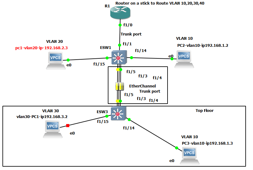
In the below lab:
We will have two switch and 1 router, and will setup with:
Trunk port = for connecting into switch or into a router only
Switch = is to create more then one of separate network known as VLANS or separate broadcast networks
Router act as Stick= to join VLANs network, to allow VLANS to communicated with each others. You will always need a router when you have more then one network (VLANS). Or you will need to buy a Layer 3 switch. Layer 3 switch has a routing feature, build into it. It can create network (VLANs) and also can do routing of VLANS.
Ether-Channel/port aggregation: It is a failover links lines, and to increase bandwidth of that two switches by combine more then one links lines into a channel.
At a Distribution Switch is where we want to set this up. Because this Switch is the main point where all other Switches are connecting into. You can also do load balancing on it.
STP (spanning tree) will be enable, to prevent loop, because we have more then one links in this setup.
protocol: PAgP = is vendor natural for ether-channel protocol setup
protocol: LACP = is a Cisco only device protocol in the Ether-Channel setup
Trunk: is need for those interfaces mode
dot1q: is Encapsulation use
int range
show int trunk
show eth sum
show etherchannel load-balance
show eth port
-DTP, VTP, CDP, STP protocol will be enable automatically part of the setup
Why doing a Router on a Stick technique?
Because both our Switch’s are a non-manage switch, also not Layer 3 type Switch and they are not capable of routing function (passing data between vlans) or has any configuration feature. Normally vlans communication is the duty of the switch, it is a lot faster. But with router on a stick technique this job is pass to the router. (Router main job is to link to other routers).
Follow the diagram above, then copy and paste below code:
Router: on a stick setup to route VLAN 10,20,30 to communicate with each other, another word to go with the switch VLAN devices info.
conf t
int f1/0.10
encapsulation dot1Q 10
ip address 192.168.1.1 255.255.255.0
no shut
exit
int f1/0.20
encapsulation dot1Q 20
ip address 192.168.2.1 255.255.255.0
no shut
exit
int f1/0.30
encapsulation dot1Q 30
ip address 192.168.3.1 255.255.255.0
no shut
exit
int f1/0.40
encapsulation dot1Q 40
ip address 192.168.4.1 255.255.255.0
no shut
end
show ip route
=====End Router setup:
Go to Switch1 (ESW1):
Adding vlan:10,20,30,40 to each switch 1 and switch 3
vlan dat
vlan 10 name IT
vlan 20 name Acct
vlan 30 name HR
vlan 40 name Exce
exit
conf t
int f1/1
sw mode tru
exi
int f1/14
sw mode acc
sw acc vlan 20
exi
int f1/15
sw mode acc
sw acc vlan 10
end
-switch 2 (ESW3): manually adding vlan 10,20,30,40
vlan dat
vlan 10 name IT
vlan 20 name Acct
vlan 30 name HR
vlan 40 name Exce
exit
conf t
int f1/14
sw mode acc
sw acc vlan 10
exi
int f1/15
sw mode acc
sw acc vlan 30
end
====Next, Port Channel (Ether channel, multiple links lines) on both switches. We’re going to setup 1 single Po links. Just 1 links coming out of the switch.
Please see this article if you want to learn how to setup more then one Po.
swtich 1:
conf t
ip routing
int range f1/3 – 5
switchport mode trunk
switchport trunk allowed vla all
channel-group 1 mode on (active)
!channel-pro lacp
exit
inter port-chan 1
switchport trunk encapsulation dot1q
switchport mode trunk
exit
——
Swtich 2 (ESW3): setup Port Channel
conf t
ip routing
int range f1/3 – 5
switchport mode trunk
switchport trunk allowed vla all
channel-group 1 mode on (passive)
!channel-pro lacp
exit
inter port-chan 1
switchport trunk encapsulation dot1q
switchport mode trunk
end
===Next, add IP address manually to the PC, VPC as below. We can do DHCP lab later.
PC1 VLAN 10:
ip 192.168.1.3/24 192.168.1.1
PC2 VLAN 10:
ip 192.168.1.2/24 192.168.1.1
—-
PC 3 VLAN 20:
ip 192.168.2.3/24 192.168.2.1
Troubleshooting:
-make sure you use the right IP for each PC with different VLANs.
–Trunk port is use on the switch to switch and to router.
sh ip int br
sh etherchannel ?
sh et su
sh mac
-While you doing a ping -t : P 192.168.1.3 -t
between pc on different switch to see the ping is still work, by go into the switch and shut that ether-channel interface line down one by one.
